· 

RaspberryPi CM4用5V入力電源回路

RaspberryPi CM4を5V入力で動作させたい時の電源回路についてです。

  • 安価なUSB Type-AのACアダプタを採用したかったり、
  • USB Type-A出力のモバイルバッテリも大容量化していたり、
  • USB PDで5Vが3A仕様になっていたり、

などなど、、でRaspberryPi CM4も5Vで動作させたいときの回路です。


5V直接をRaspberryPi CM4やUSB VBusに使える?

RaspberryPi CM4の入力定格は最低4.75Vとなっています。

また動作時の消費電力は通常約1.4Aとなっています。

5Vをコンバータ無しで直接RaspberryPi CM4に入力するのは厳しいと思われます。

外部に出力するUSB VBusなども加えるとさらに厳しいです。

よって、5V-5Vのboost, buck-boostタイプの昇降圧コンバータを採用するのが良いかと思われます。


TPS63806YFFR(TI製)

buck-boostタイプの昇降圧コンバーです。

仕様は以下のとおりです。

入力電圧範囲 : 1.3V~5.5V

出力電圧範囲 : 1.8V~5.2V

出力電流:2A(過渡電流2.5A対応)


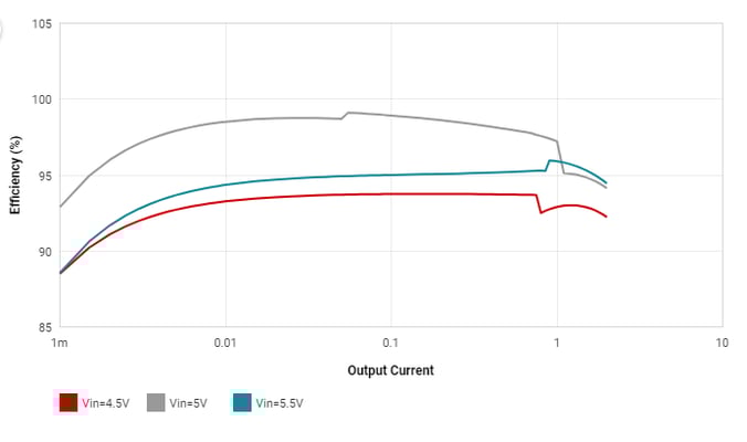
TIのWEBBENCHの結果は以下のとおりです。(なぜかSimulateができず波形生成はできませんでしたが。。)

WEBBENCHの計算条件は以下のとおりです。

  • 入力電圧 4.5V~5.5V
  • 出力電圧 5V
  • 出力電流 2A

Name Value Category Description
Vout 5 V System Information    Operational Output Voltage
IC Tolerance 5 mV IC IC Feedback Tolerance
Cin IRMS 156.64 mA Capacitor Input capacitor RMS ripple current
Cin Pd 24.54 µW Capacitor Input capacitor power dissipation
Cout IRMS 884.64 mA Capacitor Output capacitor RMS ripple current
Cout Pd 2.38 mW Capacitor Output capacitor power dissipation
L Ipp 542.63 mA Inductor Peak-to-peak inductor ripple current
Ipp percentage 22.79% Inductor Inductor ripple current percentage (with respect to average inductor current)
L Pd 43.27 mW Inductor Inductor power dissipation
Duty Cycle 16.00% System Information Duty cycle
Efficiency 92.20% System Information Steady state efficiency
Frequency 2.52 MHz System Information Switching frequency
IC Tj 57.09 °C IC IC junction temperature
ICThetaJA 34 °C/W IC IC junction-to-ambient thermal resistance
IC Pd 796.86 mW IC IC power dissipation
Pout 10 W System Information Total output power
Iin Avg 2.41 A IC Average input current
IC Ipk 2.62 A IC Peak switch current in IC
Mode CCM System Information Conduction Mode
Vout p-p 10.44 mV System Information Peak-to-peak output ripple voltage
Total Pd 842.59 mW Power Total Power Dissipation
FootPrint 66 mm² System Information Total Foot Print Area of BOM components
Vin 4.5 V System Information Vin operating point
Iout 2:00 AM System Information Iout operating point
Cin Pd 24.54 µW Power Input capacitor power dissipation
Cout Pd 2.38 mW Power Output capacitor power dissipation
L Pd 43.27 mW Power Inductor power dissipation
IC Pd 796.86 mW Power IC power dissipation
Vout Actual 4.93 V System Information Vout Actual calculated based on selected voltage divider resistors
Vout Tolerance 2.83% System Information Vout Tolerance based on IC Tolerance (no load) and voltage divider resistors if applicable
Total BOM $1.90 System Information Total BOM Cost
BOM Count 7 System Information Total Design BOM count
セル2
   

回路図

今回はPWMモードで使用します。

TPS63806YFFRを2個使用し、1つはRaspberryPi CM4用、もう一つは外部に出力するUSB VBus 5V用としました。

入力に2SJ687を入れているのは突入防止用となります。

もし入力がUSBであった場合100uFまでは問題なく使えるので突入防止は必要ないのかもしれませんが

さまざまな電源ユニットを使用した際に挙動がおかしくなるのが怖くて念のため保険でいれています。

ENピンには常時通電の補助電源の回路からオンオフができるようにしています。

さらに2段目に10 kohmと 1 uFを挿入しています。

これはboost, buck-boostタイプの昇降圧コンバータの特徴で起動時に最大電流が流れることへの対策で、

2個同時に最大電流が流れないように起動のタイミングをずらしています。


プリント基板パターン

TPS63806YFFR周辺のみで回路図の一部(入力のFETやヒューズやEMIFILや100uF)は入っていません(別のブロックのため)